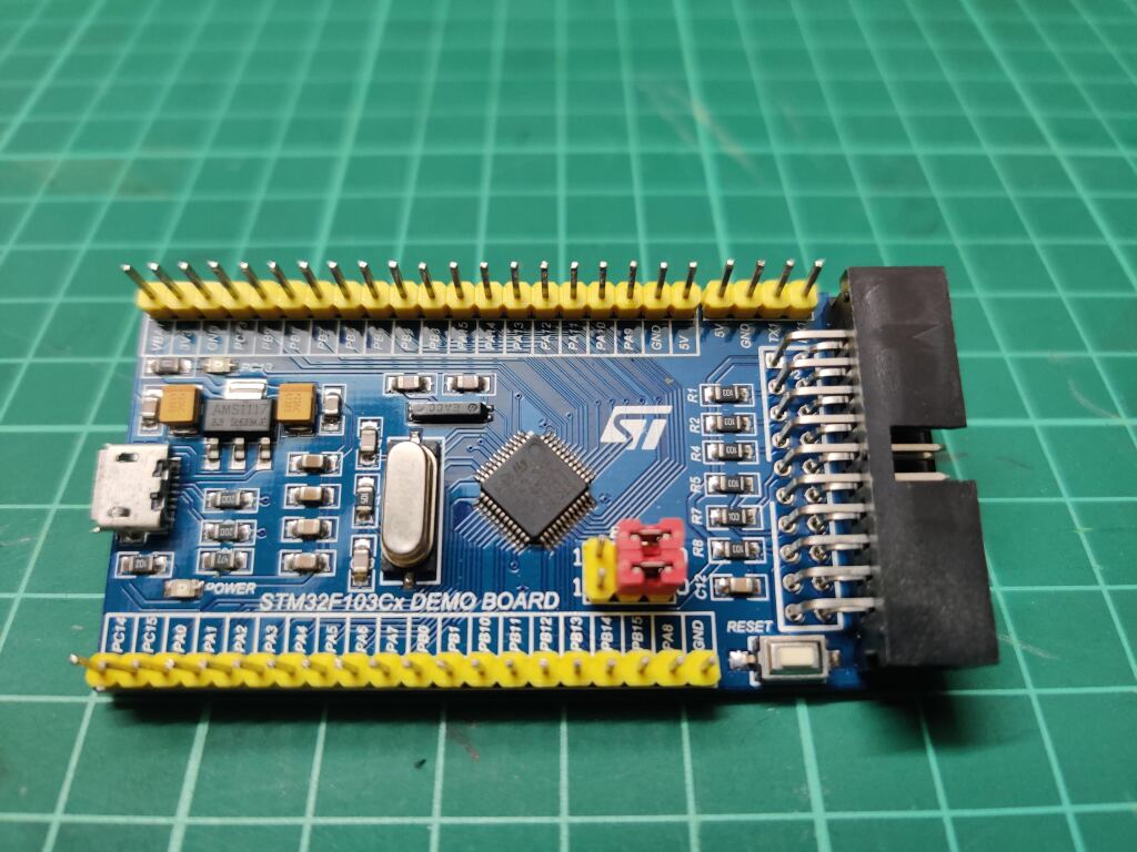
Some years back, as part of evaluating boards for my robotics team, I had picked up a cheap STM32 board off amazon. I remember being excited about it being dirt cheap and having arduino support.
Due to not having done much research, i was not that particular about which version of the board to buy. I sorted by price and picked the cheapest one.
This was a BIG mistake. The days after i received the package were quite annoying as the damn thing wouldn't work. Period. I had gotten ST-Link V2 for programming which was not cooperating. This was somewhere in the 2015-17. I had a bunch of other boards to test, and this particular one went back in the box.
Fast Forward to a week back. Covid has been hard on all of us. One more thing it gave us is a lot of time which was previously used up by travelling. I bought a shelve to clean up and organise my electronics. After finding this board, i decided to give it another try.


Attempts to find any documentation on the board layout proved futile. In the years since the purchase, it seems that the board model was discontinued...
Thankfully the on the other side there were pin-outs and comparing with other boards for the same chip. I was able to program using ST Link.
This is the connection that is needed for the same.


| Board Pins | ST-Link V2 pins | Wire Colour in above Pic |
| PA13 | SWDIO | Green |
| PA14 | SWCLK | Blue |
| 3.3V | 3.3V | Purple |
| GND | GND | Grey |
Better Connection Solution?
There is a bug while using USB on this board that essentially renders the USB transceiver in a buggy state after a soft reset. As of now, the only fix I have found is unplug and replug both the USB and st link pins.
This issue happens if the USB is used by say, a Virtual COM port (CDC) by your code. This essentially means the serial port does not work after programming the device. Instead a complete power cycling by re-plugging all power sources is required.
The current pin out is a pain to remove and reinsert. Hence the need for a connector that can be easily removed and inserted.
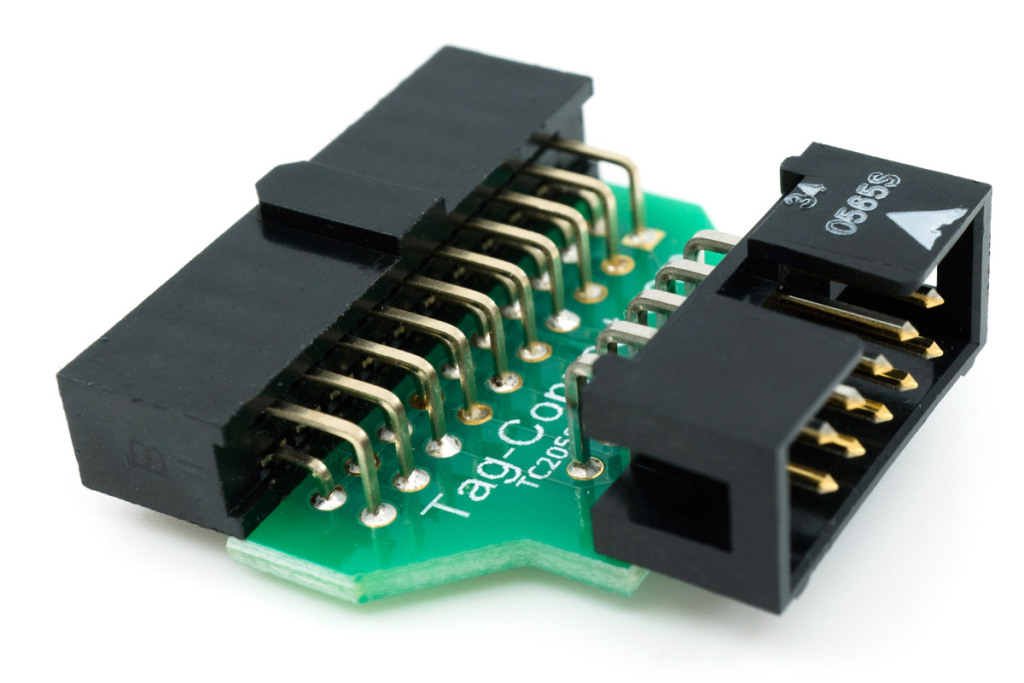
Looking into the Pin out of similar boards, I found that the big black connector is essentially a JTAG 20 pin connector.
JTAG 20 pin to 10 Pin usable?
Unfortunately the knockoff ST link V2 does not use a standard JTAG interface....
Prices of getting the cheapest stuff, I guess.
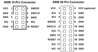
Looking at the Pin outs for the JTAG 20 pin and the Chinese Connector.


The Pin out for knockoff ST-Link is


Cheapest Solution?
Buy 2 IDC cables, 10 pin and 20 pin. Something like this. and connect them together.
This costs like 100 rs total, getting online.
P.S. The Red coloured wire is number one in the Pin-out. The rest alternating between odd and even numbers


Results


Does it look good? No.
Does it work? Yepp.
Lesson Learned? Chinese stuff is cheap for a reason.
